Effective design and planning for cable hauling projects
22 May, 2018
By Charles Cole (American Polywater) and Lindsay Taylor (TEN Group)
The majority of premature medium and high voltage cable failures result from factors related to their installation. For cables hauled into duct, a high proportion of such failures are due to high tensions or sidewall pressures generated during installation that impact the asset reliability over time. Good conduit design and installation practices minimize the risk of cable damage and can reduce project installation costs significantly.
Tension and Sidewall Pressure Estimation
The generation of tension in a cable when installed into a duct is accurately estimated using a set of equations developed in 1953 by R.C Rifenburg1. These Pulling Equations estimate tensions of cables in different duct configurations such as straight horizontal or inclined sections, horizontal bends and various vertical bend types where cables are either pulled up or down through them.
Cable installation specifications and guidelines published many years ago often use simplified versions of these pulling equations to estimate tension and appropriate work methods. The inaccuracies they introduce into tension calculations often lead to overly conservative estimates that increase cable installation costs, or concerningly compromise the long-term performance of the electrical grid when installed at higher than necessary tension. It is recommended that Rifenburg’s Cable Pulling Equations be used to minimize uncertainty and to optimize cable installation design.
Introduction to coefficient of friction
The coefficient of friction2 (COF) is a measure of the generation of friction between two objects in contact and rubbing against one another. When the COF is high, the forces needed to move these objects in contact are higher. For example, a wooden block that weighs 5 kgs is placed on a steel plate. A string is used to pull the block across the plate. A force is imparted on the string to drag the block across the metal surface. Let’s say the pulling force on the string is 2 kgs to move the block across the steel surface. The COF is defined as the ratio of this pulling force to the weight of the wooden block, this is 2÷5, or 0.4. On the other hand, a rubber block of 5 kgs pulled across the steel plate might require a greater pulling force on the string, say 5 kgs. In this case, the COF is 1 (5÷5c). What’s important to note from these examples is that there is no single coefficient of friction. The friction coefficient varies with different rubbing surfaces and weights.
The friction coefficient in cable pulling continues to depend on cable jacket, conduit, and lubricant types. “General” coefficients don’t mean much. The most accurate tension estimates come from friction coefficients specific to the cable jacket, conduit material and pulling lubricant used in the installation. These are the critical factors to consider in the development of a cable pull plan.
In the case of cable in conduit, neither the cable nor the conduit is flat. There may also be more than one cable, which results in complex interactions between the cables themselves. Pulls are not straight so forces; other than gravity, occur in conduit bends. Furthermore, the use of lubricants changes the friction coefficient.
Lubricants to reduce COF
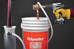
The purpose of pulling lubricants is to reduce the COF and therefore, the generation of friction between the cable and duct. This, in turn lowers tension and sidewall pressures on the cables during installation. Lower tension allows for faster hauling speeds and longer installation distances, both which minimize project costs. This is achieved with fewer pulls and associated equipment set-ups, the use of smaller and lower cost hauling equipment, the construction of fewer pulling bays, and lower investment in cable jointing where drum lengths allow. The proper specification of cable pulling lubricants is critical to the realization of these reductions.
The specification of the best suited cable pulling lubricants will optimize friction reduction and ensure compatibility of the lubricant with duct and jacket materials. Physical characteristics such as the lubricant’s cable wetting capability, chemical compatibility and functionality in the presence of water are just some of the many factors that affect overall lubricant performance. Meeting established international product and testing standards which quantify these factors ensures that the lubricant will perform as planned so as not to damage cable and equipment during installation. Adherence to such standards is critical to the optimization of overall cable network performance.
Considerations in the development of a pull plan
- Duct Geometry - This includes starting/ending points, the length and vertical displacement of straight sections, the location, direction, radii and curvature of duct bends, and the potential location of pulling/joint bays, cable pushers and other related structure or hauling equipment used in the pull.
- Materials & Equipment- including duct and cable jacket materials, rollers, winches, cable pushers, back tensions off drums and cable lubricant (and the resulting COF for its interaction with all materials)
- Tension & Sidewall Pressure Generation - The application of the appropriate physical equations to correctly model the tension and sidewall loading is critical to accurate planning and optimal cable network design.
Pull planner software for designers and installers
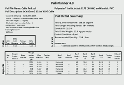
It is recommended that a program designed specifically for underground cable installation which incorporates the full set of Rifenburg’s equations and the latest COF data be used whenever possible. American Polywater’s PullPlanner®4.0 can be used to accurately estimate tensions and volume of appropriate lubricant to use. The PullPlanner®4.0 incorporates updated COF data, even for new jacket technologies such as Low Smoke Zero Halogen (LSZH) and utilizes the Pulling Equations to quantify the effects that changes in elevation or the vertical orientation of raceway bends have in tension generation. It can be used to determine whether ancillary installation equipment is required and where structures such as joint or pulling bays should be placed. The PullPlanner®4.0 also facilitates the calculation of tensions in large radius bends common to duct systems under roadways, railbeds and bodies of water.
Proper software tools can and should be used to optimize duct design in the planning phase. We typically see ductwork designs that incorporate expensive additional pulling vaults, that we later calculate can be pulled straight through. Saving on the construction of a $10,000 pulling vault simply by specifying a lubricant is a common reality. The PullPlanner®4.0 incorporates the full set of the Pulling Equations, up to date COF data and other functions for the accurate and effective estimation of tension and sidewall pressures generated on the cable when installed in an underground duct system.
Successful Case Study
A NSW contractor engaged TEN to provide Pull Planner data for a 132kV cable run. The cable run was 980m and was designed to limit joints and joint bays saving the client tens of thousands of dollars in unnecessary cost. Using the pull planner software, the customer was able to ascertain that the cable haul was feasible and fell well under the installation limits of the cable, as long as the Polywater J lubricant was utilised to achieve that COF. The recommended volume of lubricant feature in the Pull Planner allowed the contractor to know the exact amount to use, the application rate and provided a quantifiable cost to the job.
Conclusion
The understanding of how tension and sidewall pressures are generated during the installation of medium to high voltage cables is critical to the pull planning process. The safety, efficiency and economic return of underground cable hauling operations are better estimated when the appropriate data is incorporated. These include up to date COF data that reflect recent duct, cable jacket and lubricant advances, as well as, cable specifications that quantify maximum allowable tensions and sidewall pressures for the cable being installed.
To find out how TEN can save you time and money on your next cable hauling project, or to learn more about American Polywaters Pull-Planner software and market leading cable lubricants, contact Lindsay Taylor on 0400 968 238.
References:
- Rifenburg, R.C. 1953. Pipe line design for pipe type feeders, published in: Transactions of the American Institute of Electrical Engineers, Part III: Power Apparatus and Systems
- Wikipedia, 2018. Coefficient of Friction, retrieved from: https://simple.wikipedia.org/wiki/Coefficient_of_friction
|


